GPS Repeater: Antenna and Coaxial Cable Specification

To ensure that a GPS repeater installation works properly, the system must satisfy certain requirements.
The selection and correct installation of system components will make all the difference and ensure great results.
Signal level calculation
The base requirement is to achieve signal gain of at least +16 dB from outdoors to repeater input.
Example: if the antenna LNA inserts 40 dB gain and the RF240 cable is 30 meters long, the overall signal gain from antenna to repeater input will be as follows.
Assume signal frequency is 1575 MHz:
- Antenna gain +40 dB
- Cable loss –10 dB
- Overall link gain is 40 – 10 = +30 dB
Which is perfect as the repeater input should be at least 16 dB higher than the outdoor signal level.
The antenna
 The GNSS/GPS antenna has a built-in low noise amplifier (LNA) which boosts the signal before it travels down the cable.
Typically the antenna is a Tallysman device, with a gain factor of 35 to 40 dB.
The LNA requires DC power, which is obtained from the GPS repeater at the other end of the coaxial cable.
The repeater emits 5V DC through its RF connector, which travels up the cable to power the LNA.
The location where the antenna is installed is important. It should ideally be in clear space, at the highest available point, with a full 360 degree view of the sky.
Good antenna placement ensures optimal GNSS/GPS signal reception, which provides the repeater with the best quality signal input.
This is covered in the installation guide.
The coaxial cable
The coaxial cable causes signal loss through attenuation, resulting in a drop in signal levels over its length.
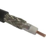
For cable lengths up to 45 meters, we specify RF240, which is a direct equivalent to LMR240.
RF240 has a solid copper core and is double-screened, ensuring a low loss characteristic while being extremely flexible and immune to ElectroMagnetic Interference (EMI).
At 1575 MHz, the frequency of GPS L1 signals, the loss incurred is 0.3 dB per meter.
Which means that RF240 is a great alternative to the commonly available RG58 cable, which inserts 0.6 dB per meter, has a stranded copper core, and has a single earth screen.
For distances longer than 45 meters, we have a number of options.
We can specify RF400, which is similar in construction to RF240, but is physically bigger and heavier.
RF400 can be used for cable runs up to ~70 meters without amplification.
By comparison, RF240 has an outer diameter of 6 mm, while RF400 measures 10 mm.
Alternatives
 For longer distances between antenna and repeater, we can insert a GNSS inline amplifier to boost the signal.
The amplifier should be installed as near to the antenna as practically possible.
This ensures the signal input to the amplifier is strong and noise-free before it is launched down the coaxial cable.
Even with an inline amplifier, it is generally not practical to install cable over distances longer than about 100 meters, especially if the cable has to be installed in ducts and risers near high voltage AC mains cables, for example.
In which case we can use GPS-over-fibre technology to increase the distance to several kilometres, if required.
Fibre optic cable is made from an inert material, and signals carried within are immune to ElectroMagnetic Interference (EMI).
More details of GPS over fibre technology here.
For more information on any of the technologies mentioned here, please get in touch.