How to extend an antenna cable with GPS over fibre technology
Sometimes the distance from outdoor antenna to indoor GPS repeater/receiver is too long to consider using coaxial cable.
Losses through attenuation, even with the use of in-line amplifiers, can adversely affect the signal, potentially making it unusable.
However, physical distance isn’t always the main issue.
If a cable must run through an area where there are high levels of electromagnetic interference (EMI), say in the vicinity of power cables, the signal can be badly affected.
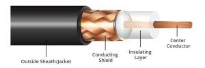
Low-loss coaxial cable can be expensive and difficult to install due to its thickness and weight.
For example, LMR400, a commonly used cable, is approximately 10.5 mm in diameter and weighs 10Kg per 100 meters.
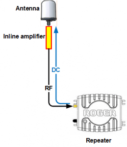
Extending the antenna cable by using amplifiers
The cable length can be increased by inserting an amplifier in-line with the cable.
The amplifier provides signal gain, with typical values in the region of 15-20dB.
This helps overcome losses caused by attenuation in the cable, and ensures that the signal input to the GPS repeater/receiver is above the minimum level specified by the manufacturer.
The amplifier is ideally placed as near to the antenna as possible, which is where the incoming signal is strongest and noise-free.
Example signal calculation
Antenna gain +40dB
Inline amplifier gain +15db
LMR240 80m cable loss @ 1575MHz -27dB
Overall link gain +28dB
The repeater needs a signal input that is at least +16dB compared to the outdoor level, so this is well within specification.
The GPS receiver emits a DC voltage through its RF connector, which is used to power the low noise amplifier (LNA) in the antenna and the in-line amplifier.
The amplifier takes what it needs (8mA in the case of the Forsberg inline amplifier) and passes the rest on to the antenna LNA.
How optical fibre can help
In the context of providing indoor GPS, the length of a coaxial cable generally is limited to around 100 meters, due to the effects of attenuation and increased noise.
Even a well-screened, low loss coaxial cable can be affected by EMI, causing delays and data packet corruption.
By comparison, the distance from antenna to receiver can be up to 10km over single mode fibre.
Optical fibre is an inert material, based on glass (silica) or plastic materials, making it immune to the external effects of RFI/EMI.
Hence it can be installed near high voltage power cables without any unwanted interference affecting the signal.
Optical fibre cable is thin and lightweight and can be installed more easily than a thicker, low loss coax.
Components of a GPS over fibre system
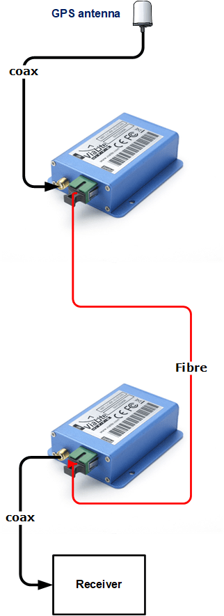
The outdoor antenna is exactly the same as used in any “standard” GPS over coax system.
FalTech usually specifies Tallysman TW3xxx antennas that have a built-in low noise amplifier (LNA), with gain ranging from 28 to 40dB.
Although, any antenna of the correct specification will work in this situation.
The antenna connects to an RF-to-optical converter (usually referred to as a TX unit) via a low-loss coaxial cable.
The TX unit converts the incoming RF signal into a light signal before transmitting it into the single-mode optical fibre.
The fibre can be a single strand cable, specifically installed for the antenna link, or a spare strand in the existing in-building infrastructure.
At the far end, the reverse happens: an optical-to-RF converter (referred to as an RX unit) converts the light signals back to RF.
DC power considerations
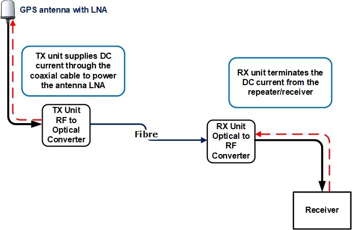 The fibre optic cable is non-conductive, which means that the GPS repeater/receiver will not be able to provide 5V DC to the antenna LNA as it would normally do with a coaxial cable connection.
The TX unit performs this function, to ensure that the LNA in the antenna receives power.
Similarly, the RX unit terminates the DC voltage from the attached receiver, by providing a resistive load that simulates an antenna present.
If the antenna fails, or is disconnected, the TX unit will sense that there is no antenna bias current drawn and assume that there is no antenna present.
The TX will switch off its laser to prevent light being unnecessarily transmitted to the fibre.
If the RX unit detects that there is no (or low) light input from the fibre, the DC load is removed from the circuit and the status LED shows red. The open circuit connector indicates to the receiver that the antenna is not present and will cause an alarm indication in most GPS receivers and time servers.
Case study
A simple, but effective, GPS over fibre link was installed in a seismology monitoring station, deep under the Austrian Alps.
The two main problems that were overcome were (1) physical distance and (2) the presence of high voltages surrounding the hydro-electric generator.
GPS over fibre applications

Lossless coax signal splitter
GPS-over-fibre input with 8 to 32 coaxial output connections.
Lossless optical signal splitter
GPS-over-fibre input with up to 64 optical connections.