Introducing the lossless GNSS/GPS signal splitter

While FalTech specialises in GPS repeater technology, we also carry some useful “ancillary” products such as in-line amplifiers and splitters.
A GPS signal splitter is hardly a new invention; they have been around for many years and are used in a wide variety of applications.
One such use is connecting multiple GPS repeater/receiver devices to a single antenna, reducing the number of antennas and coaxial cables required when making GPS signal available inside a building.
GPS signal splitters are usually available in a number of physical form factors; for example 1:2, 1:4, 1:8 and in some cases up to 1:64.
The connector type is another variable and can typically be SMA, TNC or N-Type – to name just three.
Aside from the physical construction, there are two parameters that must be considered when specifying a splitter in a network.
- Insertion loss – defined as a reduction of RF power, expressed in decibels, between a splitter’s input port and each of its output ports. A simple 1:2 splitter sends 50% of the input signal to each of the two output ports, therefore signal loss across the device is -3dB. A 1:3 splitter insertion loss is -5dB, while a 1:4 splitter insertion loss is -7dB.
- DC power handling – each of the GPS repeaters/receivers in a network emits a DC voltage from its RF connector, to power the low noise amplifier (LNA) in the active antenna. DC power is only required from one of the receivers, so it’s common for a splitter to have one DC passthrough port, with the remaining ports blocking the DC current from the other receivers.
Being aware of the insertion loss is important so that the signal level reaching any of the attached receivers is known.
How the splitter handles the DC bias voltage for the antenna is also an important consideration.
Tallysman (now Calian) lossless GNSS signal splitter
There is a range of GNSS signal splitters that is designed to counter the effects of both insertion loss and DC power handling limitations.
Available in 1:2 and 1:4 port options, the Tallysman TW16x range allows any of the attached receivers to supply DC current to the active antenna.
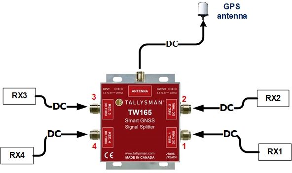 The splitter doesn’t block DC power from any of the ports; it accepts power from all attached GNSS receivers and selects power from a receiver using the following protocol.
Port #1 is given priority as long as its voltage is within the specified range (3.3 V to 12.5 V).
If port #1’s receiver is disconnected or its receiver power is outside the under-voltage or over-voltage limits, the splitter switches to the next port in numerical order.
Some of the DC power is used by a built-in signal amplifier to cancel out the insertion loss.
The TW162 (1:2) and TW164 (1:4) splitters compensate for the insertion loss, providing an overall signal gain of 0dB between input and outputs. Ordinarily, the insertion loss across a a 1:2 splitter would be -3dB, while a 1:4 splitter would insert an insertion loss of -7dB.
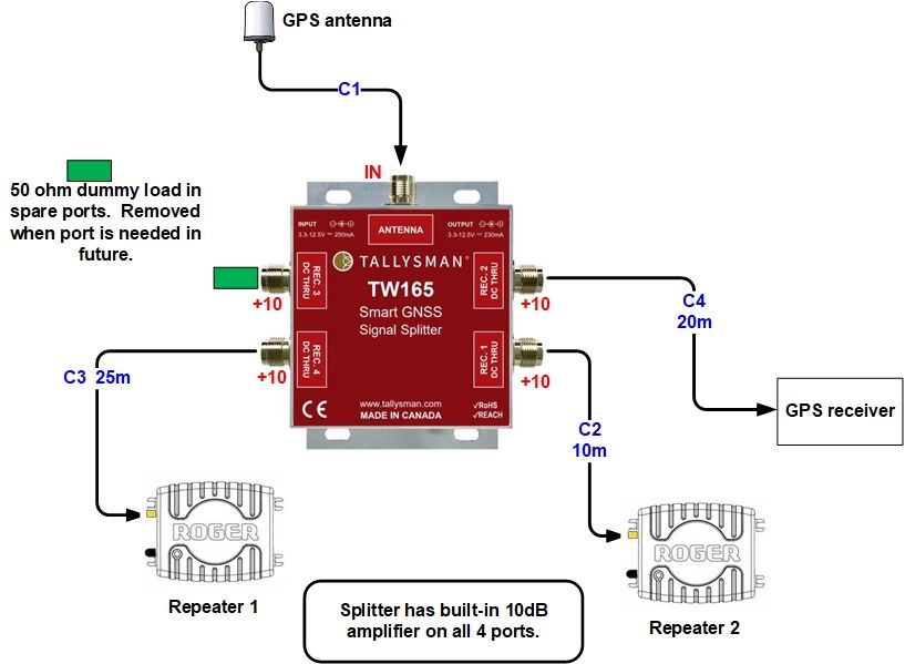
The TW163 (1:2) and TW165 (1:4) splitters compensate for the insertion loss, providing an overall signal gain of 10dB between the input and two outputs.
This amount of gain in a network may remove the need for a separate signal amplifier, as shown in the example of a recent system supplied to a customer.
To learn more, or to enquire about GPS repeater installation, contact FalTech GPS today