GPS repeater installation guide
This guide describes the installation of GPS repeater systems based on the Roger GPS standard (IP40) and waterproof (IP67) repeaters.
Covers these kits: FGPS-RP-L1-xx | FGPS-RP-L1G1GA-xx | FGPS-RP-L1L2G1GA-xx
(xx= cable length)

Each kit contains the following parts:
• Outdoor GPS antenna
• Antenna mount
• Coaxial cable
• GPS repeater unit
• Power supply with mains lead
The exact type of antenna, cable and repeater may vary slightly, depending on which system is in use. The method of installation is the same for all types.
Follow the links to antenna location | antenna installation | cable installation | repeater installation
Antenna location

The location of the antenna is one of the most important aspects of any GPS repeater installation.
The antenna should be at the highest point of the building, with an all-round 360° view of the sky.
This ensures it can receive signals from as many satellites as possible.
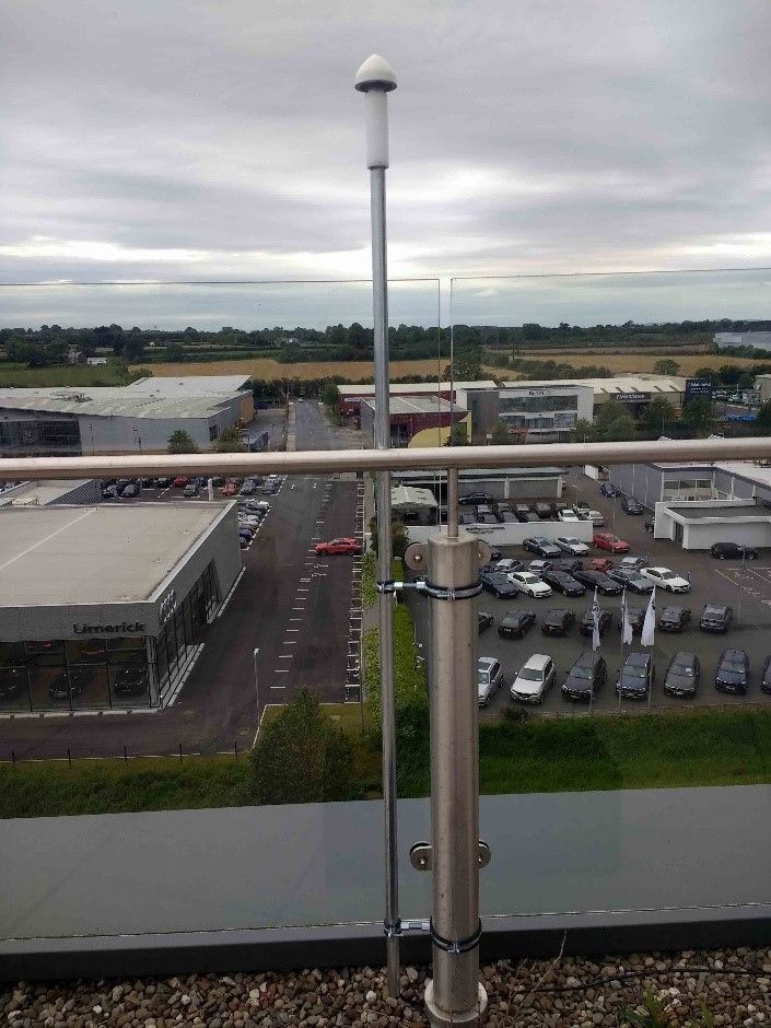
This photo shows an antenna mounted on top of an extension pole, which is fixed to the building with a stand-off bracket.
As well as having an all-round view of the sky, the antenna is located well away from the reflective steel cladding.
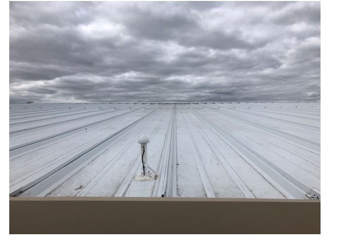
This antenna is mounted on a flat roof, using a universal mount.
It has a full 360 degree view of the sky and is at the highest point of the building.
The universal mount provides 180 degrees of adjustment and can be fixed to any vertical, horizontal or sloping surface while maintaining the antenna in a vertical position.
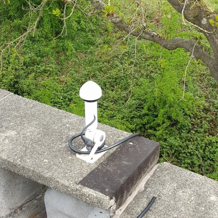
In this case it wasn’t possible to attach a mounting bracket to the building structure.
The antenna is positioned on a 2 meter length of steel tubing, which is attached to the railing,
The tubing is 25mm diameter and provides a conduit for the feeder cable as well as a robust mounting point .
Let us know if you need details of the tubing and where to obtain it.
Sometimes, even when the antenna is at the highest point, with all-round sky view, the indoor coverage can be compromised.
This antenna was installed in free space on top of a large hangar roof, but the steel cladding caused huge reflections and adversely affected the signal.
The result of that was reduced coverage area inside the building.
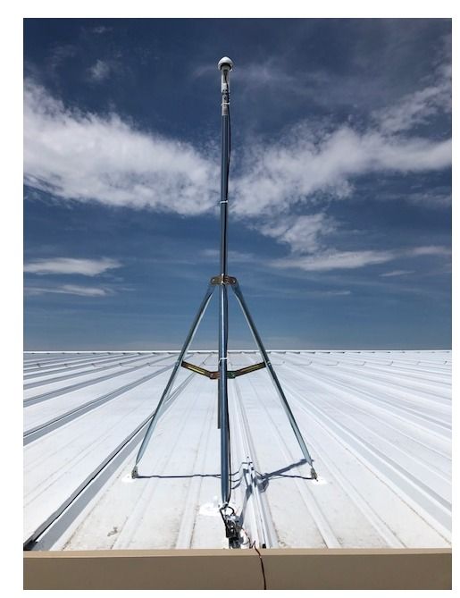
The antenna was raised above the place where it was being affected by reflections; now the repeater has a much stronger, cleaner signal input and provides a very large coverage area indoors.
Antenna installation
Systems for GPS L1 signals are supplied with a Tallysman TW3042 antenna, with TNC RF connector and built-in 40dB low noise amplifier (LNA).
Systems that cover GPS L1, GLONASS,Galileo and Beidou signals are supplied with a Tallysman TW3742 antenna, with TNC RF connector and a built-in 40dB low noise amplifier (LNA).
Systems for GPS L1, L2, GLONASS, Galileo signals are supplied with a Tallysman TW3742 antenna, with TNC RF connector and built-in 35dB low noise amplifier (LNA).
There are two types of antenna mount available; the one supplied depends on the customer’s preference.
Option 1 – universal mount
This mounting system can be used with either any Trimble or Tallysman antenna.
The antenna is secured to a white nylon tube which serves as an extension pole and a cable guide.
 The mount can be fixed to any surface – horizontal, vertical, or sloping – while allowing the antenna to face directly upwards to the sky.
The mount is supplied with four screws for secure fastening to the surface.
1. Attach the universal mount to the install surface (wall/roof) where it has an uninterrupted 360° view of the sky
2. Remove the red protective cover from the antenna RF connector and remove the two large nuts.
3. Attach the antenna head to the cable guide and tighten.
4. Attach the coaxial cable to the antenna connector and tighten by rotating the knurled nut in a clockwise direction. Take care not to twist the cable.
5. Unreel the cable and run it to the interior of the building where the repeater is located.

Option 2 – L-bracket
An alternative is to use an L-bracket that is attached to the top of a standard mounting pole.
Jubilee clips are ideal and self-tapping screws can be inserted through the pre-drilled holes into the pole. This provides extra security and prevents the L-bracket from rotating around the pole in windy conditions.
Cable installation
A coaxial feeder cable transfers the signal from the outdoor antenna to a repeater (or repeaters) inside the building.
The cable supplied is usually RF240 solid core, double-shielded coaxial, 10m, 20m, or 30m in length.
This distance can be extended if required by upgrading the cable to a type that inserts less signal loss through attenuation, and/or installing an inline amplifier to boost the signal.
The connection where the cable attaches to the antenna should be sealed to prevent water ingress.
Over time, rainwater can seep inside the outer jacket of the cable, causing corrosion, high-resistance connections, and short circuits.
Use of self-amalgamating tape is recommended; follow this link to a useful video that shows how to use self-amalgamating tape for best effect..
Take care not to install coaxial cable near electricity cables or other RF radiating systems if present.
GPS repeater installation

Roger GPS IP40 repeater for L1, GLONASS, Galileo, BeiDou
There two types of repeater to cover the GPS L1, GLONASS, Galileo and Beidou frequencies.
There is the “standard” IP40 non-waterproof device, and an IP67-rated waterproof option.
The IP40 version is the most commonly used, as it is generally installed inside a building where conditions are dry, with low humidity.
The IP67 waterproof device does not necessarily have to be installed outside.
It is useful in areas where there is high moisture content, for example a boat house or coastal property.
It is physically more robust than the IP40 version, so it is sometimes selected for use in more “industrial” areas.
It is usually supplied with a standard non-waterproof AC/DC power supply; an IP67 waterproof power supply is available as an option.
Need help with your installation?
Or call us on